When the car is parked in a straight position, it is found that the front wheel is skewed; when the car is driving, it is easy to run off, and the driver has to turn the steering wheel to one side to keep the car in a straight line. When the failure of the front wheel steering system is still unresolved, it is necessary to consider the damage of the lower control arm of the front suspension.
The main reason for the damage of the lower control arm is that the front wheel is subjected to high force when the car is running at high speed, causing the lower control arm to produce bending deformation. When the car is driving on an uneven road, the wheel is subjected to a strong lateral force to deform the lower control arm; And the inner and outer rubber bushings are damaged.
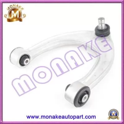
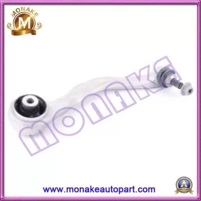
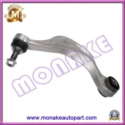
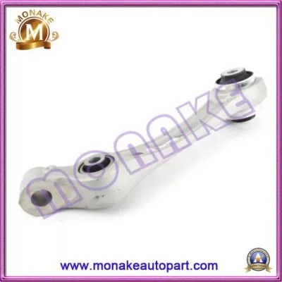
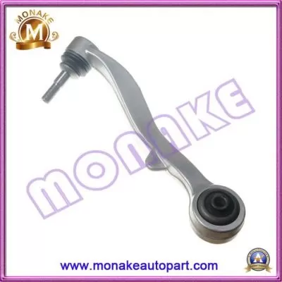
When the inspection reveals that the lower control arm is bent and deformed, the inner and outer bushing seats of the lower control arm are damaged or the inner and outer bushings are crushed and deformed or even protruded outside the bushing seat, the lower control arm or the inner and outer rubber bushings should be replaced. Remove the front control arm of the front suspension. The lower control arm dismantling diagram is shown in Figure 3-18.
Dismantle and repair the lower control arm should pay attention to:
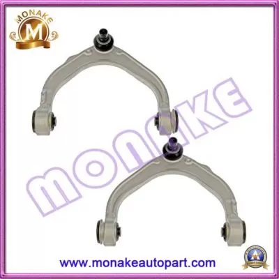
(1) The left and right sides of the lower control arm are different and cannot be used interchangeably. The assembly position is the lower control arm inner bushing seat facing up and the outer bushing seat facing forward.
(2) Each part of the front suspension is locked with a lock nut. Replace all self-locking nuts when reassembling, the tightening torque of the inner bushing self-locking nut 2 of the lower control arm is 85N.m; the tightening torque of the self-locking nut 1 for reinforcement is 40N.m1 for fixing the rubber bushing The tightening torque of the lock nut 7 is 20N.m; the tightening torque of the outer bushing self-locking nut 18 is 110N.m; the tightening torque of the self-locking nut 15 at the outer end of the fixed control arm is 65N.m; the lateral stabilizer bar is assembled The tightening torque of the self-locking nut 3 of the seat is 105 N.m.
(3) When disassembling and installing the stabilizer bar, the car body should be lifted to relax the front suspension and the stabilizer bar to pull out or press the stabilizer bar. The stabilizer bar bushing 8 should be coated with talcum powder.
(4) Special tools should be used for disassembly and installation of the front frame front bushing 5 and the sub-frame rear bushing l4. When installing, apply a layer of grease and press the bushing to the end. Pay attention to the auxiliary car during installation. For the alignment of the axle of the car, tighten the fixing bolts in the order of right rear, rear left, front left and front right. The tightening torque of the fixing bolt is 65N.m, and then tighten for 1/4 week.
(5) The hexagonal bolt 13 for installation on the outside of the lower control arm should be replaced. The direction of the bolt head should be backward. After installation, it should be carefully checked to avoid falling off during driving, and the front axle of the car loses the lateral support point.
(6) In the use of the car, attention should be paid to the fixing of each rubber bushing, the deformation of the lower control arm and the deformation of the sub-frame, and the problems should be promptly dismantled and repaired. All operations should be carried out under the condition of disassembly. The car is welded and calibrated, otherwise it will get worse.

Xiamen Monake Import And Export Co., Ltd. located in Xiamen Special Economic Zone in China. Which is specialized in supplying Engine Mount ( Transmission Mount ), Strut Mount, Center Support, Control Arm, etc. For various cars in Asia, European, American and Japanese brands.


QR Code

 nancy@monakeautopart.com
 +86-592-5986102